

Setting up the Revolution Pi
This page explains how to prepare a KUNBUS Revolution Pi (RevPi) for logiccloud. You configure the I/O modules with PiCtory, activate the configuration, and install logiccloud Control on the device. After these steps, the RevPi signals are available to a RevPi connection.
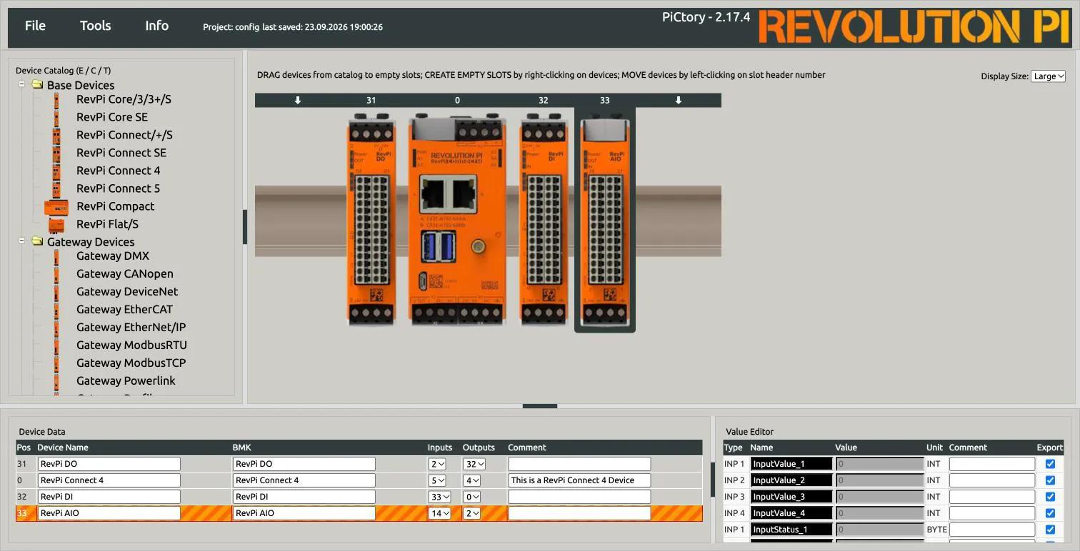
The screenshots show a RevPi Connect 4 with a RevPi DO, a RevPi DI and a RevPi AIO module.
The steps are the same for other RevPi base modules and I/O modules.
This guide was tested with the RevPi Bookworm image 260611-revpi-bookworm-arm64-default and PiCtory 2.17.4.
Before you start
Section titled “Before you start”You need:
- A RevPi base module (for example RevPi Connect 4 or RevPi Core) with the RevPi Bookworm image from KUNBUS.
- The I/O modules mounted on the DIN rail and connected to the base module with the PiBridge connectors.
- 24 V power for the base module and for every I/O module.
- A network connection between the RevPi and your computer.
- The IP address of the RevPi. Your router or DHCP server shows it.
- The password of the
piuser. It is printed on the sticker on the side of the housing.
1. Open the RevPi web interface
Section titled “1. Open the RevPi web interface”- In your browser, open
https://<device-ip>. - The RevPi uses a self-signed certificate. Accept the browser warning for this address.
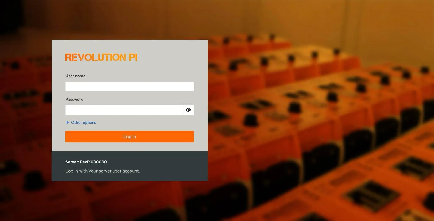
- Log in with the user
piand the password from the sticker.
- In the left menu, select Revolution Pi.
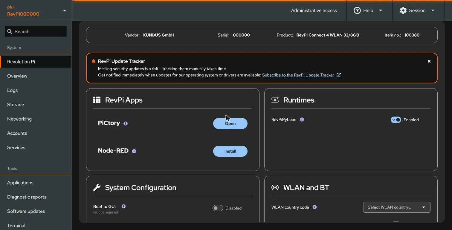
The page shows the device data, the RevPi Apps and the Runtimes settings.
Set a fixed IP address (recommended)
Section titled “Set a fixed IP address (recommended)”By default, the RevPi gets its IP address from a DHCP server. The address can change after a restart. Use a fixed address, or a DHCP reservation in your router, so that you always find the device at the same address.
- In the left menu, select Networking. The Interfaces table shows the network interfaces and their addresses.
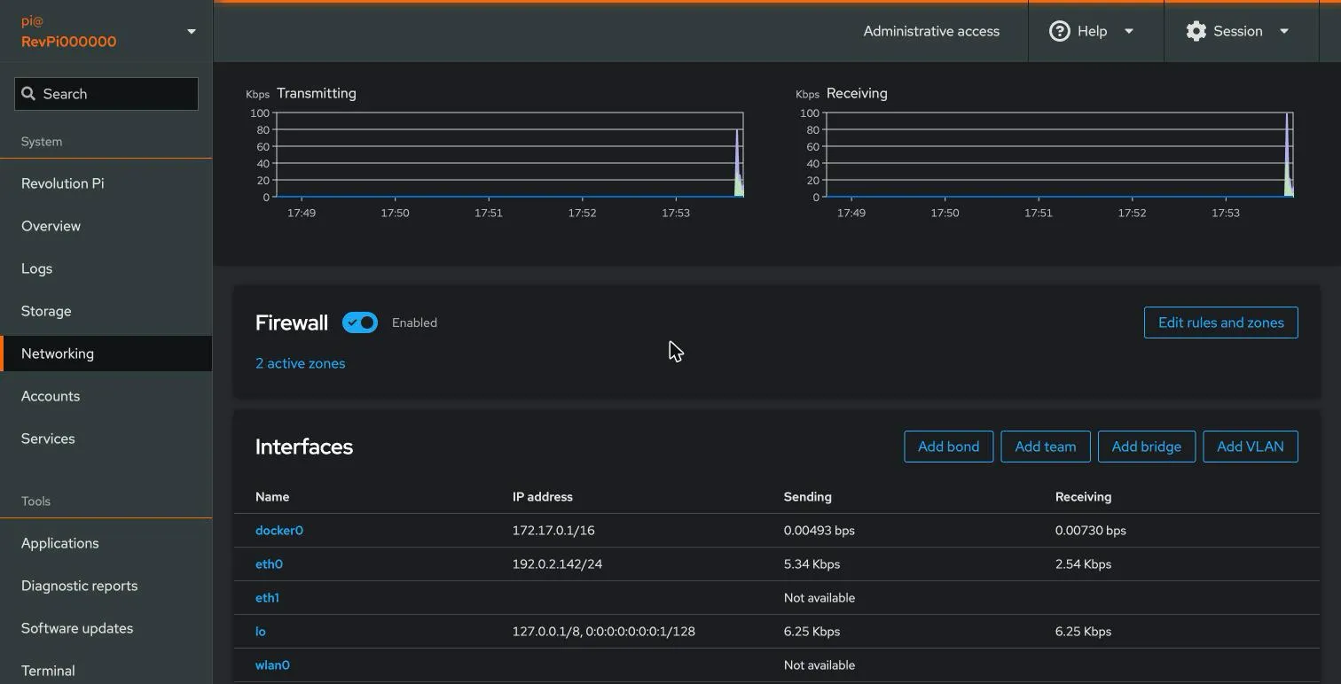
- Click the interface that is connected to your network, for example
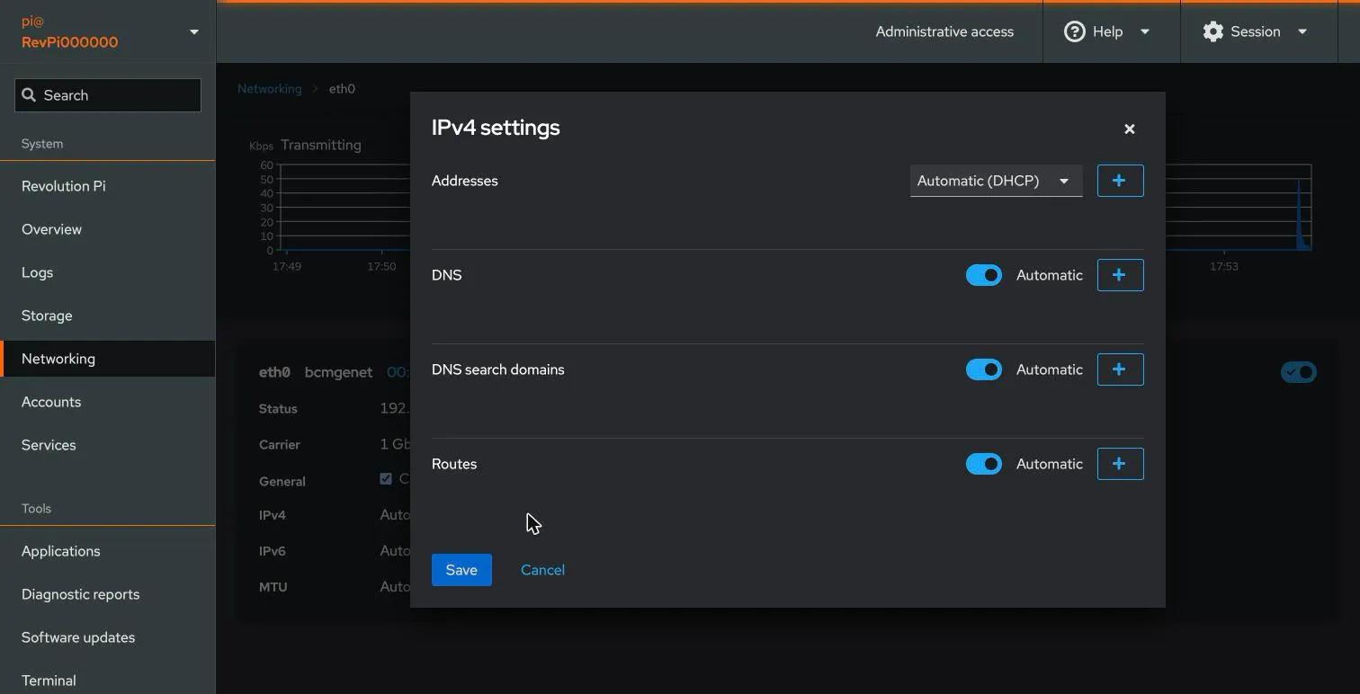
eth0. - Next to IPv4, click edit.
- In Addresses, change
Automatic (DHCP)toManual. Enter the address, the prefix length and the gateway. - To set the DNS server by hand, switch off Automatic next to DNS and add the server with +.
- Click Save.
2. Open PiCtory
Section titled “2. Open PiCtory”Next to PiCtory, click Open. PiCtory opens in a new browser tab.
PiCtory has four areas:
- Device Catalog (left): all RevPi modules that you can place.
- Rack (center): the DIN rail with the configured modules.
- Device Data (bottom left): the configured modules with their position numbers.
- Value Editor (bottom right): the signals of the selected module.
3. Place the modules
Section titled “3. Place the modules”Place every module in the same order as on the DIN rail.
The base module always has position 0.
Modules to the right of the base module get the positions 32, 33, and so on.
Modules to the left get the positions 31, 30, and so on.
- In the Device Catalog, open the folder Base Devices and drag your base module to the empty rail.
- Open the folder I/O Devices.
- Drag each I/O module to the slot where it is mounted on the DIN rail.
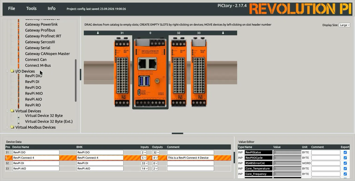
When you drop a module on a free slot, PiCtory gives it the next position number and selects it.
In the following example, a RevPi AIO was dropped to the right of position 33 and got position 34:
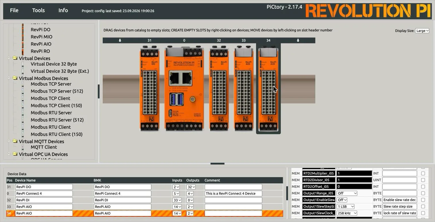
A new module has these properties:
- The Export column is not selected for its signals. logiccloud does not need it, see Check the signal names.
- If a signal name already exists on the device, PiCtory adds a suffix to the name, for example
RTD2Offset_i05. See Troubleshooting.
Right-click a module to open its context menu:
- Insert slot LEFT and Insert slot RIGHT create an empty slot next to the module.
- Delete removes the module from the configuration.
- Show Datasheet opens the KUNBUS datasheet of the module.

4. Check the signal names
Section titled “4. Check the signal names”Click a module in the rack. The Value Editor shows its signals:
| Column | Meaning |
|---|---|
| Type | INP (input), OUT (output) or MEM (configuration value of the module) |
| Name | The signal name. logiccloud uses this name in the mappings. |
| Value | The default value |
| Unit | The data type in PiCtory (BOOL, BYTE, WORD, INT, DWORD) |
| Export | Export flag for other programs. logiccloud does not use this flag. |
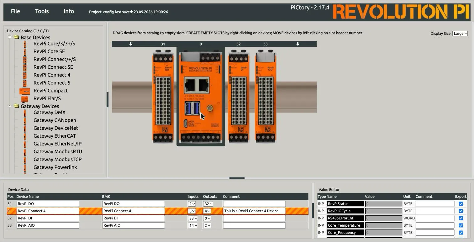
You can rename a signal in the Name column. A name for logiccloud must:
- start with a letter,
- contain only letters, digits, underscores and dots,
- have a maximum of 31 characters,
- be unique on the device.
The logiccloud RevPi connector reads every signal by name, also when Export is not selected.
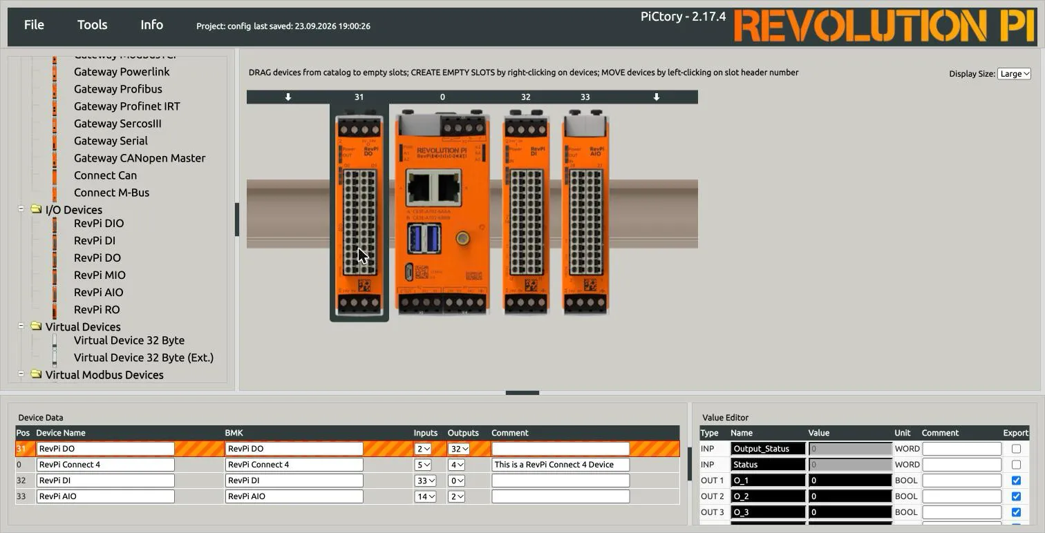
In the following example, Output_Status and Status of the RevPi DO are not exported, and logiccloud can still read them:
Analog modules
Section titled “Analog modules”For a RevPi AIO module, set the range of every input and output before you use the values.
Select the module and scroll the Value Editor to the MEM rows. The ranges are drop-down lists.
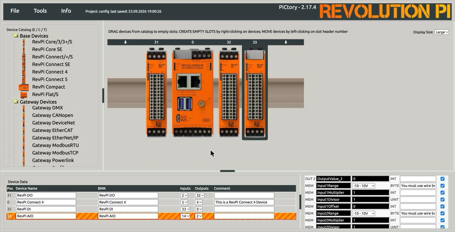
Inputs (Input1Range to Input4Range): select the range of the sensor.
The options are -10 - 10V (default), 0 - 10V, 0 - 5V, -5 - 5V, 0 - 20mA, 0 - 24mA, 4 - 20mA and -25 - 25mA.
With Input1Multiplier, Input1Divisor and Input1Offset (and the same values for the other inputs), you can scale the value on the module.
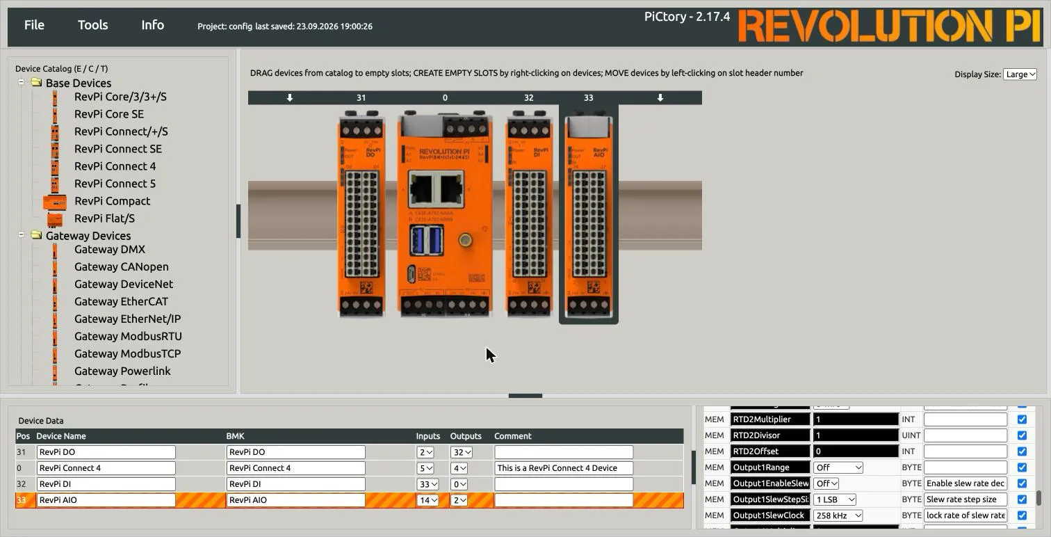
Outputs (Output1Range and Output2Range): the default is Off.
With Off, the analog output does not drive a signal, even when logiccloud writes OutputValue_1 or OutputValue_2.
Select a voltage or current range before you use the output.
RTD inputs (RTD1Type, RTD1Wiring and the same for RTD 2): select PT100 or PT1000, and 2-wire, 3-wire (default) or 4-wire.
5. Save the configuration
Section titled “5. Save the configuration”Open File and select Save as Start-Config.
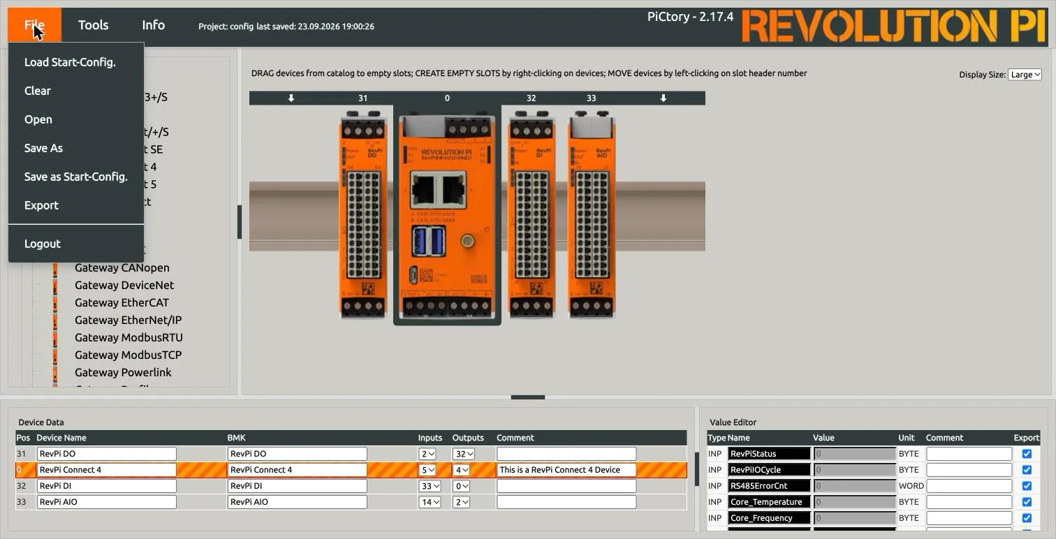
PiCtory saves the file /var/www/revpi/pictory/projects/_config.rsc. The link /etc/revpi/config.rsc points to this file.
logiccloud reads the signals from this file.
6. Reset the driver
Section titled “6. Reset the driver”The saved file has no effect until the piControl driver loads it again.
Open Tools and select Reset Driver. Confirm the dialog.
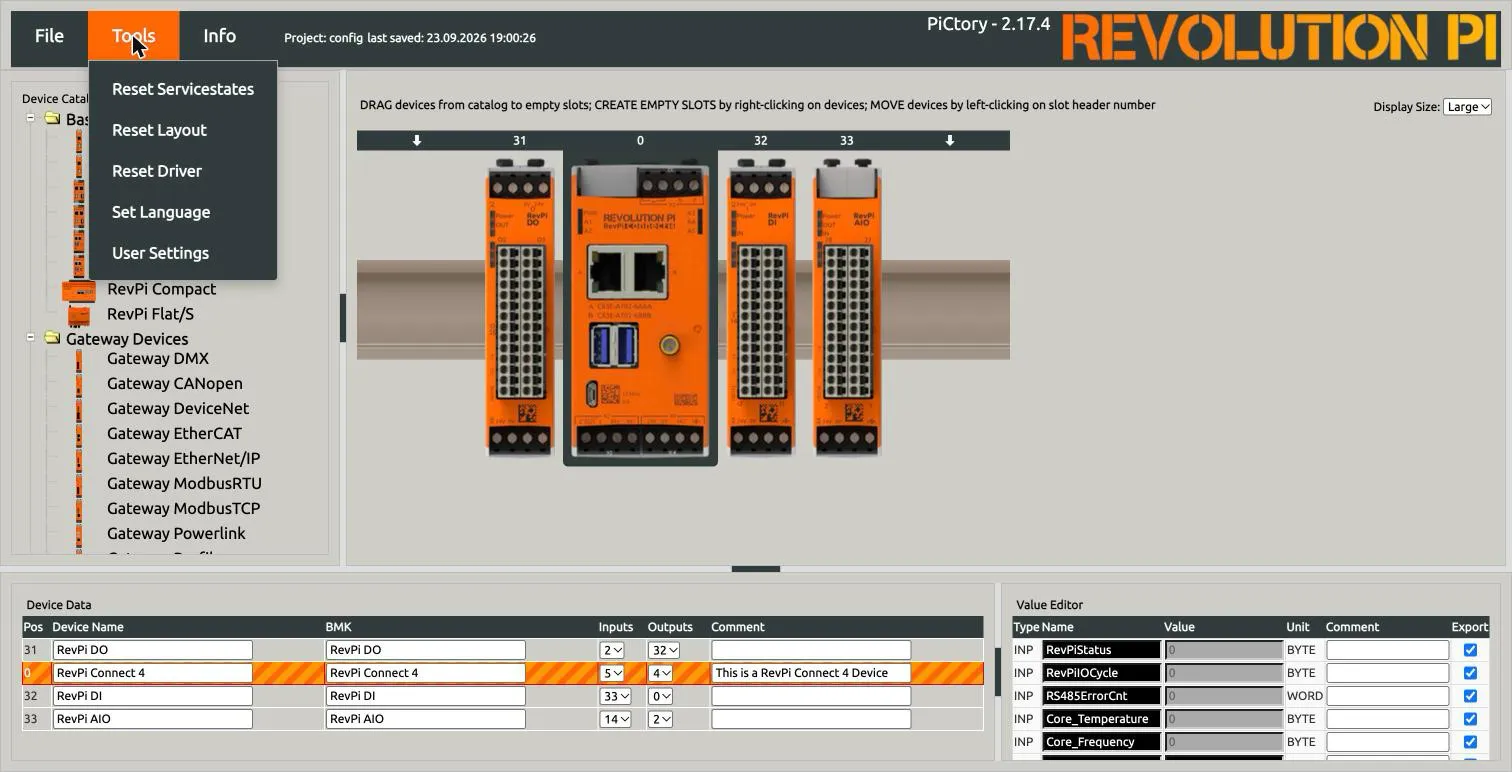
Repeat steps 5 and 6 after every change in PiCtory. If a logiccloud runtime already runs on the device, also restart the runtime. The connector reads the signal names when it starts.
7. Check the configuration on the device
Section titled “7. Check the configuration on the device”Connect to the RevPi with SSH and list the modules:
ssh pi@<device-ip>piTest -dEvery module must show Module is present:
Found 4 devices:
Address: 0 module type: 136 (0x88) RevPi Connect 4 V1.0Module is present     input offset: 113 length: 6    output offset: 119 length: 7
Address: 32 module type: 97 (0x61) RevPi DI V1.5Module is present     input offset: 126 length: 70    output offset: 196 length: 18...
If a module shows NOT CONFIGURED, its position in PiCtory does not match the DIN rail. See Troubleshooting.
More commands are described in Checking signals with SSH.
8. Install logiccloud Control
Section titled “8. Install logiccloud Control”- In the logiccloud portal, create a device with the vendor KUNBUS and your RevPi type.
- Install logiccloud Control on the RevPi with the Quick Install command from the device binding dialog. See logiccloud Control for all steps.
The installation script detects the RevPi. It gives logiccloud Control access to:
- the piControl driver (
/dev/piControl0), to read and write the signals, - the PiCtory configuration (
/etc/revpi/config.rsc, read only), to browse the signals.
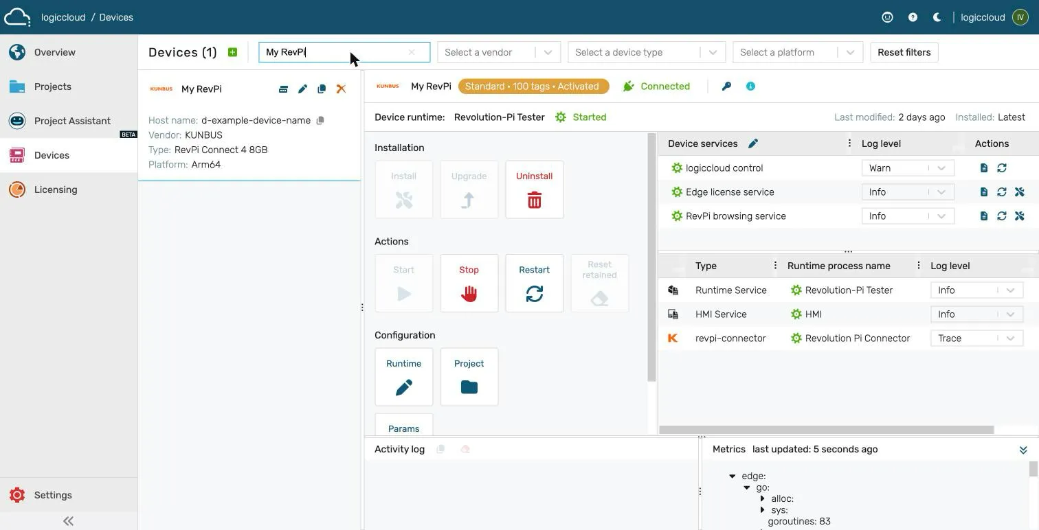
After the installation, the device is shown as Connected in the portal:
9. Keep the driver installed
Section titled “9. Keep the driver installed”The piControl driver is a kernel module from the package picontrol. Without it, no RevPi signal is available.
- Do not remove the package
picontrol. - Before you confirm
sudo apt autoremove, read the list of packages. Cancel ifpicontrolis in the list. - After a kernel update, restart the RevPi and check the driver with
piTest -d.
Next steps
Section titled “Next steps”- Create a RevPi connection in your project.
- Browse the RevPi signals and add them to the mappings.
- Check the signals with SSH.