Inputs & Outputs
Inputs and outputs are the interface between the PLC program and the outside world. Inputs are used to read data from sensors or other devices, while outputs are used to control actuators or other devices. In logiccloud, inputs and outputs are defined directly in the code using a specific syntax, depending on the intended usage and behavior.
There are several aspects of the I/O configuration that can be defined in the code:
- Direction:
IN,OUT, orIN_OUTto specify whether the variable is an input, output, or both. - HMI Visibility:
HMIorNO_HMI(default) to indicate whether the variable should be visible in the HMI. - Internal:
INTERNALto indicate that the variable is for internal use only and should not be used in connectors. Typically, such variables are used for HMI-only values. - Reset policy (only for outputs):
NO_RESETto specify that the variable should not be reset during a program reset.RESET_DEFAULT(default) to specify that the variable should be reset to its default value during a program reset.RESET_TO <constant value>to specify that the variable should be reset to a specific constant value during a program reset.
The syntax for defining inputs and outputs in the code follows the patterns shown in the examples below:
VAR_INPUT    varA, varB: INT { IN }; // Input variables with default reset policy and no HMI visibility    varC: BOOL { IN HMI }; // Input variable visible in HMI    varD: REAL { IN INTERNAL }; // Internal input variableEND_VAR
VAR_OUTPUT    varE: INT { OUT RESET_DEFAULT }; // Output variable with default reset policy    varF: BOOL { OUT HMI NO_RESET }; // Output variable visible in HMI and not reset on program reset    varG: REAL { OUT RESET_TO 3.14 }; // Output variable reset to 3.14 on program resetEND_VAR
VAR    varH: INT { IN_OUT }; // Input/Output variable with default reset policy and no HMI visibility    varI: BOOL { IN_OUT HMI }; // Input/Output variable visible in HMI    varJ: REAL { IN_OUT INTERNAL }; // Internal Input/Output variableEND_VAR
In these examples, various input and output variables are defined with different configurations for direction, HMI visibility, and reset policies. This allows for flexible and precise control over how the PLC program interacts with external devices and systems.
I/O Variable names
Section titled “I/O Variable names”The names of the generated access variables will be the same as the variable names defined in the code. For example, if you define an input variable named sensorValue, the corresponding access variable will also be named sensorValue. This naming convention helps maintain consistency and makes it easier to identify and use the variables in the HMI or other external systems.
Variables defined as IN_OUT will have two access variables generated: one for input and one for output. The naming convention for these variables will be as follows:
- For the input part:
<variable_name>_INPUT - For the output part:
<variable_name>_OUTPUT
Nested I/O Definitions
Section titled “Nested I/O Definitions”In addition to defining inputs and outputs at the top level of a POU, logiccloud also supports nested I/O definitions within function blocks. This allows for more organized and modular code, especially when dealing with complex data types. For example:
FUNCTION_BLOCK FB_MyFunctionBlockVAR_INPUT    inputVar: INT { IN };END_VARVAR_OUTPUT    outputVar: BOOL { OUT };END_VARVAR    ioVar: STRING { IN_OUT HMI };END_VAREND_FUNCTION_BLOCK
PROGRAM MyProgramVAR    fbInstance1: FB_MyFunctionBlock;    fbInstance2: FB_MyFunctionBlock;END_VAREND_PROGRAM
In this example, the function block FB_MyFunctionBlock has its own input, output, and internal I/O variable. When instances of this function block are created in the program MyProgram, each instance will have its own set of I/O variables as defined within the function block. This encapsulation helps in managing complexity and enhances code readability.
When using nested I/O definitions, the generated access variable names will include the instance name to ensure uniqueness. In the above example the following access variables will be created:
fbInstance1_inputVarfbInstance1_outputVarfbInstance1_ioVar_INPUTfbInstance1_ioVar_OUTPUTfbInstance2_inputVarfbInstance2_outputVarfbInstance2_ioVar_INPUTfbInstance2_ioVar_OUTPUT
This naming convention ensures that each instance’s I/O variables can be easily identified and accessed without conflicts.
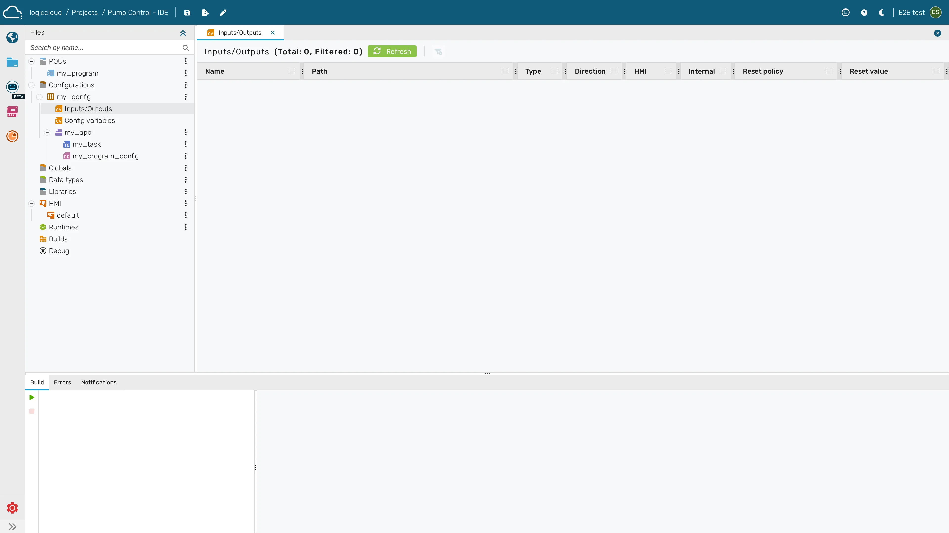
I/O Variable List
Section titled “I/O Variable List”The variable list is updated as soon as the project is saved. If the code contains errors, the variable list will not be updated until the errors are resolved and the project is successfully saved. This ensures that the variable list accurately reflects the current state of the code and prevents inconsistencies that could arise from unresolved errors.
Refreshing the access variables manually
Section titled “Refreshing the access variables manually”The access variables shown on the Inputs/Outputs tab are generated from your code. They do not always regenerate on their own while you are editing — for example when you have just changed an I/O declaration but the change has not yet been transpiled. To force the list to reflect the current code, use the Refresh from code button at the top of the Inputs/Outputs tab (the circular-arrow / refresh icon).
Pressing Refresh first saves any unsaved (dirty) files, then re-runs the transpiler over the project and rebuilds the access-variable list from the resulting I/O definitions. While the refresh is in progress the button shows a spinning icon and is disabled to prevent overlapping refreshes. If the code currently contains errors, the list is left unchanged until the errors are fixed and the refresh succeeds. The same Refresh from code action is available on the legacy access-variables grid.
If there are access variables defined with earlier versions of logiccloud, they will be preserved in the variable list even if they are not defined in the current code. This allows for backward compatibility and ensures that existing configurations remain intact. The legacy access variables are highlighted in the list.
If a variable is defined in the code and matches an existing legacy access variable, the existing access variable will be updated to reflect the new definition from the code. This ensures that any changes made in the code are accurately represented in the access variable list, maintaining consistency between the code and the access variables used in the HMI or other external systems.
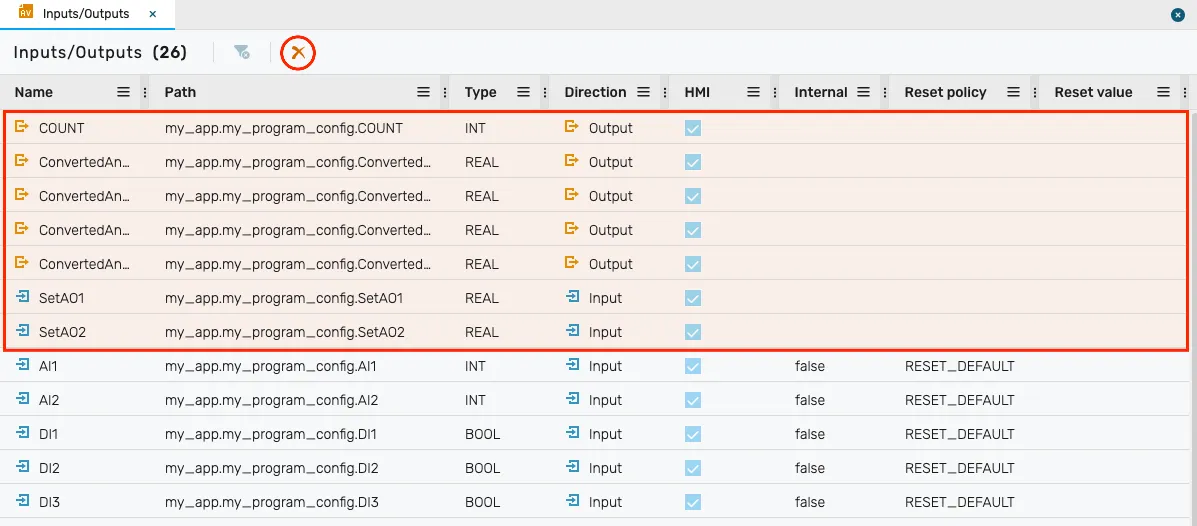
The legacy access variables are highlighted in yellow in the list above. To remove all legacy access variables that are no longer defined in the code, you can use the “Remove Legacy Access Variables” button (highlighted in the screenshot). This will clean up the variable list and ensure that it only contains access variables that are currently defined in the code.